Extras
Contents
- 1 Creating Accounting Shares
- 2 Creating Address Type
- 3 Creating a Business Unit
- 4 Creating a Company
- 5 Creating a Component
- 6 Creating a Contact
- 7 Creating a Contact Method Type
- 8 Creating a CPU Type
- 9 Creating a Discount Program
- 10 Creating a Domain
- 11 Creating an Influence
- 12 Creating an Influence Template
- 13 Creating a Legend
- 14 Moving an Influence or Link Location on a Map
- 15 Creating a Layer
- 16 Attaching a Link to a Link Layer
- 17 Applying a Layer to a Map
- 18 Customize Display Options When Viewing a Map
- 19 Opening a Link on a Map
- 20 Creating a Number Format Template
- 21 Creating a Payment
- 22 Creating a Payment Type
- 23 Creating a Physical Disk
- 24 Creating a Power Plug
- 25 Creating a Power Plug Ampere
- 26 Creating a Power Plug Backup Source
- 27 Creating a Power Plug Circuit
- 28 Creating a Power Plug Type
- 29 Creating a Power Plug Voltage
- 30 Creating a Product
- 31 Creating a SAN Connection
- 32 Creating a SAN
- 33 Creating Service Infos
- 34 Creating a Service Tier
- 35 Creating a Shape
- 36 Creating a SNMP V1 Template
- 37 Creating Tags
- 38 Creating a Timing Template
- 39 Creating a Trend Template
- 40 Uploading an Image
- 41 Creating a URL Scrape Template
- 42 Creating a Virtual Machine Datacenter
- 43 Importing from a File
- 44 Creating a Graph Line
- 45 Creating a Physical Disk RAID
- 46 Creating a Physical Disk Speed
- 47 Exporting a File
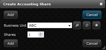
An accounting share is a way to track what department or function of the business owns or is making payments for a piece of hardware. You will need to know the following information to create an accounting share:
- Business unit or business department having ownership of the device
- Number of shares that business unit owns
Instructions
- Select a business unit from the “Business Unit” drop-down menu or create a new “Business Unit” record by clicking the star button (see Creating a Business Unit section for instructions)
- Examples: Accounting, Production, Marketing, etc.
- Enter the desired amount of shares into the “Shares” field
- Click “Add”
Creating Address Type
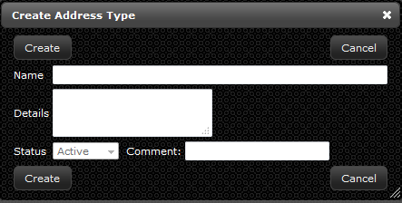
Creating an address type is required for each operating system, usually defined as IPv4 or IPv6. The address type is not considered the actual address.You will need to know the following information before creating an address type:
- Whether the address type is an IP-V4 or IP-V6
Instructions
- If you are already in the “Create Address Type” window skip to step 3a. If you are not in that window continue to step 2.
- On the navigation menu (left-hand side) click “Extras” and click “Address Types” this will open a new tab titled “Address Types”
- In the address types tab, (in the upper left-hand corner) click the “Create” button. A new window will open up called “Create Address Type”
- Enter the address type in the field titled “Name”
- Examples: IP Address, IP Address (location-based), etc.
- Enter any additional information about the address type in the “Details” field
- Click “Create”
Creating a Business Unit
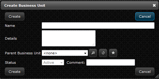
A business unit or business department is a great way to track ownership or affected areas of the organization that touch a specific piece of hardware, software, or virtual machine. A business unit uses the parent-child relationship like a hardware product. This can be utilized for accounting and tracking purposes of the asset. You will need to gather the following information when creating a business unit:
- Name of the business unit or function you wish to create
- A parent business unit, if any
Instructions
- If you are already in the “Create Business Unit” window skip to step 3a. If you are not in that window continue to step 2.
- On the navigation menu (left-hand side) click “Extras” and click “Business Unit” this will open a new tab titled “Business units”
- Within the business unit tab, (in the upper left-hand corner) click the “Create” button. A new window will open up called “Create Business Unit” or if you are in the “Create Hardware” window, service tab in the business unit section click the star button.
- Enter the company name in the “Name” field
- Examples: Target, Best Buy, etc.
- Enter any additional information about the name of the company in the “Details” field
- Click “Create”
- In the business unit tab, click the “Create” button or if you are in the “Create Hardware” window, service tab in the business unit section click the star button
- Enter the department in the “Name” field
- Examples: Marketing, Accounting, etc.
- Enter any additional information about the department name in the “Details” field
- Select the company name in the “Parent Business Unit” drop-down menu
- Examples: Target, Best Buy, etc.
- Click "Create"
Creating a Company
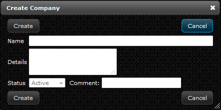
Creating a company is a way to distinguish the physical history and payment history of an asset in the event of a merger and acquisition or any other event which would involve transfer of ownership. You will need to know the following information before creating a company:
- Name of the company you wish to create
Instructions
- If you are already in the “Create Company” window skip to step 3a. If you are not in that window continue to step 2.
- On the navigation menu (left-hand side) click “Extras” and click “Companies” this will open a new tab titled “Companies”
- Within the companies tab, (in the upper left-hand corner) click the “Create” button. A new window will open up called “Create Company.”
- Enter the company name in the field titled “Name”
- Enter any additional information about the company in the “Details” field
- Click "Create"
Creating a Component
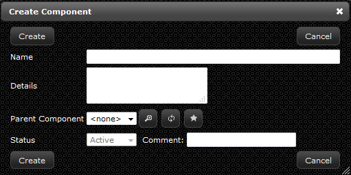
Components tracking is a great way to record what is contained within a specific piece of hardware you are creating. The component information can give you insight into how much of a resource you are utilizing and consuming in your data center. It tracks everything from power to memory to peripheral cards inserted into the back of your servers. You will need to gather the following information to create a component record for your hardware:
- Memory in GB for the hardware
- Number of logical disk volumes
- Number of network interfaces for the hardware
- Number of management interfaces for the hardware
- Number of CPU’s in the hardware
- Other components, utilizing the parent-child relationship, located within the hardware
- Physical disks
- SAN connections
- Number and type of power plugs
Instructions
- If you are already in the “Create Component” window skip to step 3a. If you are not in that window continue to step 2.
- On the navigation menu (left-hand side) click “Extras” and click “Components” this will open a new tab titled “Components”
- In the components tab, (in the upper left-hand corner) click the “Create” button. A new window will open up called “Create Component.” If you are in the “Create Hardware” window, component tab in the component section click the star button.
- Enter the peripheral name of the components in the “Name” field
- Examples: Network Card, PCIE Card, etc.
- Enter any additional information about the peripheral in the “Details” field
- Click “Create”
- In the components tab, click the “Create” button or if you are in the “Create Hardware” window, component tab in the component section click the star button.
- Enter the ports in the “Name” field
- Examples: port numbers
- Enter any additional information about the ports in the “Details” field
- Select the peripheral in the “Parent Component” drop-down menu
- Examples: Network Card, PCIE Card, etc.
- Click "Create"
Creating a Contact
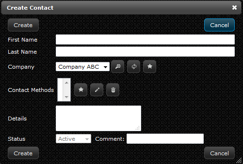
A contact is utilized when referring to an asset, specifically a piece of hardware. This is the organization and person you would contact if the asset has a disruption of service or experiences a failure or outage. You will need to gather the following information when creating a contact:
- Type of contact; electrician, service provider, maintenance, etc.
- Name of the contact; first and last name, company the contact works for, and contact method (see Creating a Contact Method Type for instructions)
Instructions
- If you are already in the “Create Contact” window skip to step 3a. If you are not in that window continue to step 2.
- On the navigation menu (left-hand side) click “Extras” and click “Contacts” this will open a new tab titled “Contacts”
- Within the contact tab, (in the upper left-hand corner) click the “Create” button. A new window will open up called “Create Contact”
- Enter the first name of the contact in the “First Name” field
- Enter the last name of the contact in the “Last Name” field
- Select which company the contact is associated with in the “Company” drop-down menu or create a new “Company” record by clicking the star button (see Creating a Company section for instructions)
- Add a contact method by clicking the star button. In the “Create Contact Method” window enter the following:
- Enter a “Type” from the drop down menu or by clicking on the star button to create a new “Type” record. (see Creating a Contact Method Type section for instructions)
- Enter a phone number or email for the contact method in the “Value” field
- Click “Add”
- Enter any additional information for the contact in the field titled “Details”
- Click "Create"
Creating a Contact Method Type
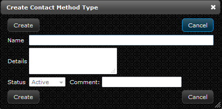
A contact method type provides the means to reach the point of contact for an asset, typically for hardware. The contact method type refers to the email or phone number used to get in touch with the person. You will need to gather the following information when creating a contact method type:
- What mode of contact is preferred for reaching this person; email, SMS, mobile phone, etc.
Instructions
- If you are already in the “Create Contact Method Type” window skip to step 3a. If you are not in that window continue to step 2.
- On the navigation menu (left-hand side) click “Extras” and click “Contact Method Types” this will open a new tab titled “Contact Method Types”
- Within the contact method type tab, (in the upper left-hand corner) click the “Create” button. A new window will open up called “Create Contact Method Type.”
- Enter the name of the contact method type in the “Name” field
- Enter any additional information about the contact method type in the field titled “Details”
- Click "Create"
Creating a CPU Type
Instructions
- If you are already in the “Create CPU Type” window skip to step 3a. If you are not in that window continue to step 2.
- On the navigation menu (left-hand side) click “Extras” and click “CPU Types” this will open a new tab titled “CPU Types”
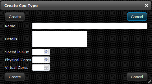
- Within the CPU type tab, in the upper left-hand corner click the “Create” button. A new window will open up called “Create CPU Type.”
- Enter the name of the CPU type in the “Name” field
- Examples: Intel Xeon E5450
- Enter any additional information about the CPU type in the field titled “Details”
- Enter the speed of the CPU type in the field “Speed in GHz”
- Enter how many physical cores the CPU type has in the “Physical Cores” field
- Enter how many virtual cores the CPU type has in the “Virtual Cores” field
- Click "Create"
Creating a Discount Program
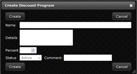
A discount program is used when referring to the service of an asset, typically hardware. Creating a discount program record is valuable for tracking what service company your dollars are going to and what deal you are receiving from a discount standpoint. You will need to gather the following information before creating a discount program record:
- Name of the discount program, for tracking purposes
- Percentage of the discount program, to know what deal has been provided by the service company
Instructions
- If you are already in the “Create Discount Program” window skip to step 3a. If you are not in that window continue to step 2.
- On the navigation menu (left-hand side) click “Extras” and click “Discount Program” this will open a new tab titled “Discount Programs”
- Within the discount program tab, (in the upper left-hand corner) click the “Create” button. A new window will open up called “Create Discount Program.”
- Enter the name of the discount program in the “Name” field
- Enter any additional information about the discount program in the field titled “Details”
- Enter a discount percent in the field called “Percent”
- Click “Create”
Creating a Domain
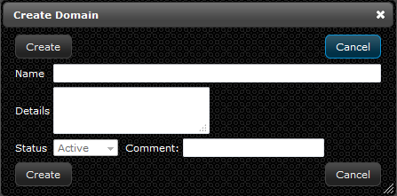
A domain record refers to a collection of devices within your network, similar to contoso.com, and helps delineate between internal devices and devices that reside in other domains. The LiveDC platform will track what domains are being utilized by which operating systems and provide ease of searching this information. You will need to gather the following information before creating a domain record:
- Name of the domain record you wish to create
Instructions
- If you are already in the “Create Domain” window skip to step 3a. If you are not in that window continue to step 2.
- On the navigation menu (left-hand side) click “Extras” and click “Domains” this will open a new tab titled “Domains”
- Within the domains tab, (in the upper left-hand corner) click the “Create” button. A new window will open up called “Create Domain.”
- Enter the name of the domain in the “Name” field
- Example: company_xyz.local
- Enter any additional information about the domain in the field titled “Details”
- Click “Create”
Creating an Influence
An influence is the way to represent what is happening to a specific data series in the data center on a map. The influence is shown by using a color scale, known as a legend, to provide knowledge around the objects real-time state. The influence’s color is affected by the data series it is connected to. As the data in the data series changes, so does the color of the influence, based upon the legend associated with the map. You will need to gather the following information before creating an influence:
- Specific data series that you would like to attach to the influence (see Creating a Data Series for instructions)
- Map that you would like to place the influence on (see Creating a Map for instructions)
- Layer of the map you will be placing the influence on (see Creating a Layer for instructions)
- Influence template that you will be using to give the influence boundaries, shape, and scale (see Creating an Influence Template for instructions)
Instructions
- On the navigation menu (left-hand side) click “Extras” and click “Layers” this will open a new tab titled “Layers List”
- Select the desired layer to place influences on from the layers list and click “Manage Influences.” This will open a new tab titled “Manage Influences.”
- Within the manage influence tab a list titled “Influence List,” where all of the influences for the desired layer will reside, will be open. Click “Create” to make a new influence.
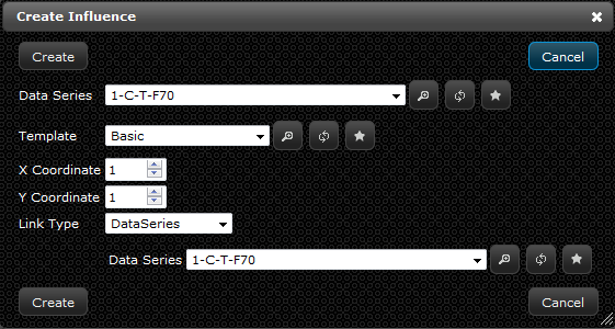
- A new window will open up titled “Create Influence”
- Select the data series you wish to correspond with the influence in the “Data Series” drop-down menu or create a new “Data Series” record by clicking the star button (see Creating a Data Series section for instructions)
- Select an influence template to define the parameters for the influence in the “Template” drop-down menu or create a new “Influence Template” record by clicking the star button (see Creating an Influence Template section for instructions)
- Define the location of the influence horizontally in the “X Coordinate” field (this can be adjusted at a later time, default: 1)
- Define the location of the influence vertically in the “Y Coordinate” field (this can be adjusted at a later time, default: 1)
- Select the type of link for the influence in the “Link Type” drop-down menu
- If data series, select the corresponding data series or create a new “Data Series” record by clicking the star button (see Creating a Data Series section for instructions)
- If hardware visual, select the corresponding hardware or create a new “Hardware” record by clicking the star button (see Creating Hardware section for instructions)
- Click “Create”
- To edit the position of an influence, either edit the specific influence from the influence list or from the map (see Editing a Map Influence for more information)
Creating an Influence Template
An influence template provides the visual boundaries that are placed around an influence for a map. Basically, the template will tell the influence what shape to take, if the pixels are going to fade at the edges, and the algorithm to follow in reference to what you are trying to display (usually will be predefined “Power2”). You will need to gather the following information before you create an influence template:
- Name of the influence template you wish to create
- What shape you are intending your influence to have (See Creating a Shape for instructions)
- Fade on the influence, basically if you want it to have hard edges or softer edges
Instructions
- If you are already in the “Create Influence Template” window skip to step 3a. If you are not in that window continue to step 2.
- On the navigation menu (left-hand side) click “Extras” and click “Influence Templates” this will open a new tab titled “Influence Templates”
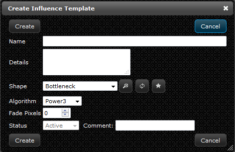
- Within the influence templates tab, (in the upper left-hand corner) click the “Create” button. A new window will open up called “Create Influence Template.”
- Enter the name of the influence template in the “Name” field
- Examples: Standard Humidity, Standard Temperature, Standard Power kW, etc.
- Enter any additional information about the influence template in the field titled “Details”
- Select what shape you want to make the influence template in the drop-down menu called “Shapes” or create a new “Shape” record by clicking the star button (see Creating a Shape section for instructions)
- Select the “Algorithm” to be applied to the shape from the drop down menu
- Default for temperature / humidity: Power2
- Default for power: Constant
- Enter a value for the “Fade Pixels” of the shape if you want soft edges when two influences collide
- The value is the number of pixels at the edge of the shape that will be softened
- Click “Create”
Creating a Legend
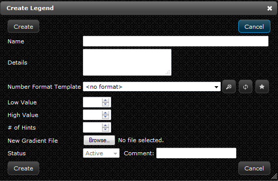
A legend is how to define the value boundaries for an influence to represent colors. The legend is seen at the bottom of a map to visually display the value range in a color scale. It all works as follows: First a data series produces a numerical value and pushes that number to the associated influence, next the influence template will give that numerical value a shape boundary, within the influence template boundary the numerical value will correspond with the legend to produce a certain color value for representation of the influence on the map. You will need to gather the following information to create a legend:
- Name of the legend you wish to create
- Number format template that corresponds with the numerical value you wish to display
- Define a low value for the legend
- Define a high value for the legend
- Define the number of hints you wish the legend to have (hints are the number of values displayed on the legend)
- Choose a gradient file to correspond with your legend (can be found at this link: http://livedcnow.com/downloads)
Instructions
- If you are already in the “Create Legend” window skip to step 3a. If you are not in that window continue to step 2.
- On the navigation menu (left-hand side) click “Extras” and click “Legends” this will open a new tab titled “Legends”
- Within the legend tab, (in the upper left-hand corner) click the “Create” button. A new window will open up called “Create Legend.”
- Enter the name of the legend in the “Name” field
- Examples: Data Center Power, Cost Per Cabinet, Data Center Temps, etc.
- Enter any additional information about the legend in the “Details” field
- Select the number format template to be used with the legend in the “Number Format Template” drop-down menu or create a new “Number Format Template” record by clicking the star button (see Creating a Number Format Template section for instructions)
- Enter value of lowest point in the “Low Value” field
- Enter value of highest point in the “High Value” field
- Enter a number of desired hints in the “# of Hints” field
- If you want to represent 0-10, you would select 11 for number of hints
- Select a gradient file to use for the legend in the “New Gradient File” section
- Click “Create”
Moving an Influence or Link Location on a Map
Instructions
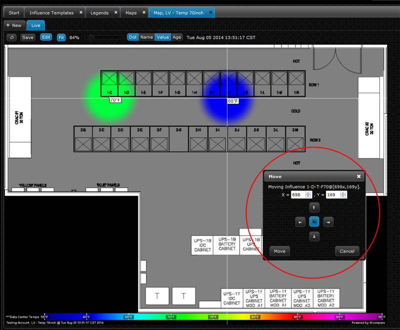
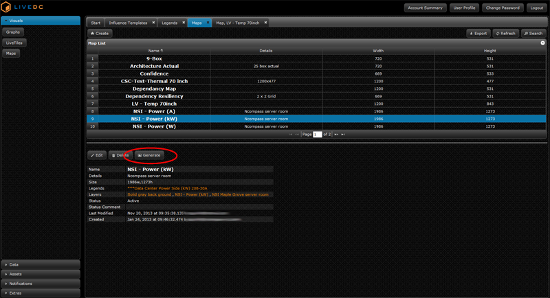
- On the navigation menu (left-hand side) click “Visuals” and click “Maps” this will open a new tab titled “Maps”
- Highlight the desired map that you want to view from the map list and click "Generate"
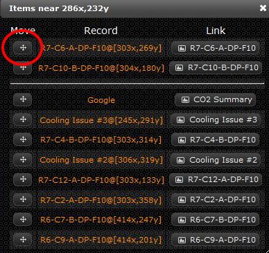
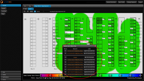
- Click near or on the influence/link desired to move, this will open a window titled “Items Near (specific X,Y coordinate)"
Creating a Layer
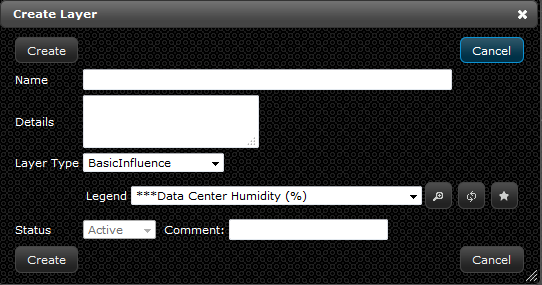
A layer is an aspect of the map that serves a very important purpose. The first layer is the solid background, which is the foundational piece for creating any map. The second layer is the layer on which the influences sit, which is usually placed in between the solid background and the floor plan layer. The third layer is a transparent floor plan layout of the data center; the top-down view of what infrastructure (cabinets, PDU’s, UPS, etc.) is located within the room. Lastly, you can add a link layer which allows you to click on the map and link out to either a URL, data series, graph, map, LiveTile, or a piece of hardware directly. This order of layering provides the capabilities to show a floor layout, 9-box model, risk assessment, etc. and the abilities to place influences on top to paint a clear picture of real-time metrics in your data center. You will need to gather the following information to create a layer:
- Name of the layer you wish to create
- What type of layer that is to be created; basic influence, image, link, or solid
- Legend you wish to correspond to the influences that will be placed on the map (see Creating a Legend for instructions)
Instructions
- If you are already in the “Create Layer” window skip to step 3a. If you are not in that window continue to step 2.
- On the navigation menu (left-hand side) click “Extras” and click “Layers” this will open a new tab titled “Layers”
- Within the layers tab, (in the upper left-hand corner) click the “Create” button. A new window will open up called “Create Layer.”
- Enter the name of the layer in the “Name” field
- Examples: Floor Plan, Cost Per Cabinet, Humidity % 10 inch, Solid Background, etc.
- Enter any additional information about the layer in the “Details” field
- Select the type of layer desired in the “Layer Type” drop-down menu
- If “Basic Influence," choose which legend to use in the “Legend” drop-down menu or create a new “Legend” record by clicking the star button (see Creating a Legend section for instructions)
- If “Image," select the appropriate image from the drop-down menu or create a new “Image” record by clicking the star button (see Uploading an Image section for instructions. Select the placement of the image from the drop-down menu.
- If “Link," no additional information is needed
- If “Solid," define the desired color and percentage of transparency in the “Color” and “Transparency Percentage” fields
- Click “Create,” you can now view your layer in the Layers List
- If you created a "Link Layer" see the next steps in section Attaching a Link to a Link Layer
Attaching a Link to a Link Layer
Instructions
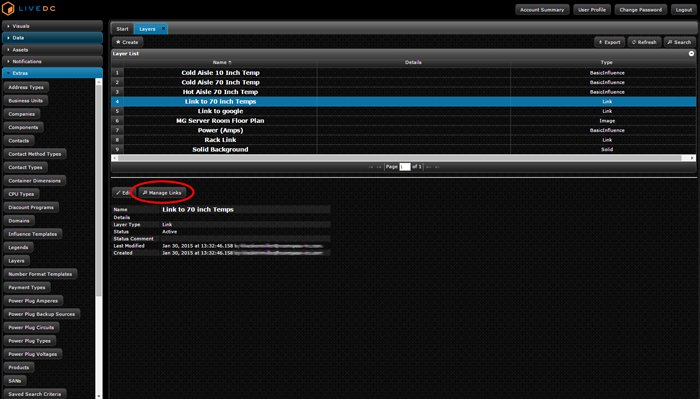
- On the navigation menu (left-hand side) click “Extras” and click “Layers” this will open a new tab titled “Layers”
- Select the desired link layer you want to add a link to from the “Layer List”. If the link layer is not created see Creating a Layer section for instructions
- On the bottom half of the screen, click "Manage Links"
- In the new tab,(in the upper left-hand corner) click the “Create” button. A new window will open up called “Create Link”
- Enter the name of the link in the “Name” field
- Example: Google, Facebook, Avg Cold Aisle Data Series, Executive Summary Map
- Enter any additional details about the link in the “Details” field
- Select the shape you want the link to have on the map from the drop down menu or create a new “Shape” record by clicking the star button (see Creating a Shape section for instructions)
- Define the location of the Link horizontally in the “X Coordinate” field (this can be adjusted at a later time, default: 1) (see Moving an Influence or Link Location on a Map section for instructions)
- Define the location of the Link horizontally in the “Y Coordinate” field (this can be adjusted at a later time, default: 1) (see Moving an Influence or Link Location on a Map section for instructions)
- Select the type of link for the link layer in the “Link Type” drop-down menu
- If URL, enter URL into the text box
- If data Series, select the corresponding data series from the drop-down menu or create a new data series record by clicking the star button (see Creating a Data Series section for instructions)
- If graph, select the corresponding graph from the drop-down menu or create a new graph record by clicking on the star button (see Creating a Graph section for instructions)
- If hardware, select the corresponding hardware from the drop-down menu or create a new hardware record by clicking on the star button (see Creating Hardware section for instructions)
- If LiveTile, select the corresponding LiveTile from the drop-down menu or create a new LiveTile record by clicking on the star button (see Creating a LiveTile section for instructions)
- If Map, select the corresponding Map from the drop-down menu or create a new Map record by clicking on the star button (see Creating a Map section for instructions)
- Click "Create"
- You have just successfully added a link to the specified layer.
- To add your new layer to a map, see section Applying a Layer to a Map for instructions
- On the navigation menu (left-hand side) click “Visuals” and click “Maps” this will open a new tab titled “Maps”
- Select the desired map you want to place a layer on from the maps list and click "Edit". This will open a new window titled "Edit Map".
- In the layers section, click the star button, and select a layer from the drop-down menu or create a new layer record by clicking on the star button (see Creating a Layer section for instructions)
- Adjust the red x’s to green check marks for attributes you want to display on the map for this layer (these attributes can be adjusted when viewing the map and will be the defaults for viewing each time this map is generated) (see Customize Display Options When Viewing a Map section for instructions)
- Adjust the text and background color for this layer
- Adjust the transparency percentage for this layer
- Click "Add"
- Click "Save"
- On the navigation menu (left-hand side) click “Visuals” and click “Maps” this will open a new tab titled “Maps”
- Select the desired map you want to view and click "Generate"
- In the upper left-hand corner click the "wrench" icon, this will open a window titled "Customize Display Options"
- From this window, you can choose which attributes to display, the color of the line, text, and background as well as the transparency percentage for any and all of the layers that comprise the current map
- On the navigation menu (left-hand side) click “Visuals” and click “Maps” this will open a new tab titled “Maps”
- Select the desired map you want to view and click "Generate"
- Click on the map near the location of the link you wish to select
- A window will open titled "Items near xx,yy"
- Find the record that you want to view the link
- Click on the link button in the link column for that record
- Name of the number format template you wish to create
- Specified type of number format template; either simple, currency, or java decimal pattern
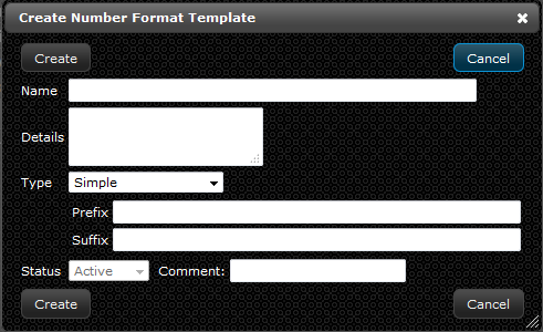
- If you are already in the “Create Number Format Template” window skip to step 3a. If you are not in that window continue to step 2.
- On the navigation menu (left-hand side) click “Extras” and select the button called “Number Format Templates” this will open a new tab titled “Number Format Templates”
- Within the number format templates tab, (in the upper left-hand corner) click the “Create” button. A new window will open up called “Create Number Format Template.”
- Enter the name of the number format template in the “Name” field
- Examples: Fahrenheit (rounded), Percent, kWh, etc.
- Enter any additional information about the number format template in the “Details” field
- Select the type of number format template in the “Type” drop-down menu
- If “Simple” type, define Prefix and Suffix
- Prefix: $, etc.
- Suffix: kW, Amps, Tons, Months
- If “Currency” type, choose “Locale” from the drop-down menu
- Default: en_US
- If “Java Decimal Pattern” type, enter the pattern in the “Pattern” field
- To create a number with a single value after the decimal, you would enter: ##.#
- Click “Create”
- Date of the payment
- Amount to be paid
- How you will be paying the payment (see Creating a Payment Type for instructions)
- Who the payment is paid by (see Creating a Business Unit for instructions)
- Who the payment is paid to (see Creating a Company for instructions)
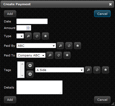
- Enter the date of when the payment for the hardware is to be paid in the “Date” field
- Enter the amount of the payment in the “Amount” field
- Select the type of payment in the “Type” drop-down menu or create a new “Payment Type” record by clicking the star button (see Creating a Payment Type section for instructions)
- Select who will be making the payment in the “Paid By” drop-down menu or create a new “Paid By” record by clicking the star button (see Creating a Business Unit section for instructions)
- Select to whom the payment is going to in the “Paid To” drop-down menu or create a new “Paid To” record by clicking the star button (see Creating a Company section for instructions)
- Add tags to the payment in the section titled “Tags” by selecting from the drop down menu and clicking the left-hand facing arrow or create a new “Tag” record by clicking the star button (see Creating Tags section for instructions)
- Enter any additional information about the payment in the “Details” field
- Click “Add”
- If you are already in the “Create Payment Type” window skip to step 3a. If you are not in that window continue to step 2.
- On the navigation menu (left-hand side) click “Extras” and click “Payment Types” this will open a new tab titled “Payment types”
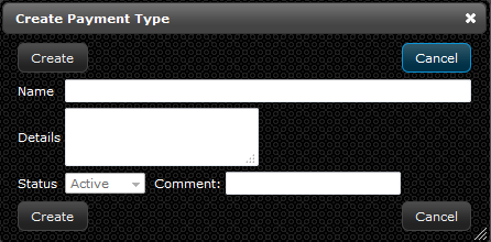
- Within the payment types tab, (in the upper left-hand corner) click the “Create” button. A new window will open up called “Create Payment Type.”
- Enter the name of the payment type in the “Name” field
- Enter any additional information about the payment type in the “Details” field
- Click “Create”
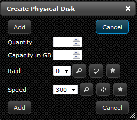
- Enter the amount of physical disks of the hardware in the “Quantity” field
- Enter the amount of capacity the physical disk has in the “Capacity in GB” field
- Select the physical disk RAID that is utilized by the hardware in the “RAID” drop-down menu or create a new “Physical Disk RAID” record by clicking the star button (see Creating a Physical Disk RAID section for instructions)
- Enter the name of the physical disk RAID in the “Name” field
- Example: Disk Controller
- Enter any additional information about the physical disk RAID in the “Details” field
- Select the physical disk speed that is utilized by the hardware in the “Speed” drop-down menu or create a new “Physical Disk Speed” record by clicking the star button (see Creating a Physical Disk Speed section for instructions)
- Enter the name of the physical disk speed in the “Name” field
- Enter any additional information about the physical disk speed in the “Details” field
- Click “Add”
- Number of power plugs for the specific piece of hardware
- Type of power plug
- Observed wattage
- Estimated wattage
- Amount of wattage displayed on the nameplate of the hardware
- Amount of ampere
- Backup source of the hardware
- What circuit the hardware is linked back to
- Amount of voltage for the hardware
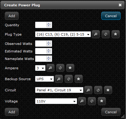
- In the window titled “Creating Hardware”, enter the amount of Power Plugs for the piece of hardware in the “Quantity” field
- Select the type of power plug in the “Plug Type” drop-down menu or create a new “Plug Type” record by clicking the star button (See Creating a Power Plug Type section for instructions)
- Enter the amount of watts observed in the “Observed Watts” field)
- Enter the amount of watts estimated in the “Estimated Watts” field
- Enter the amount of watts on the nameplate of the hardware in the “Nameplate Watts” field
- Select an ampere for the power plug in the “Ampere” drop-down menu or create a new “Ampere” record by clicking the star button (See Creating a Power Plug Ampere section for instructions)
- Select a backup source for the power plug in the “Backup Source” drop-down menu or create a new “Backup Source” record by clicking the star button (See Creating a Power Plug Backup Source section for instructions)
- Select a power circuit for the power plug in the “Circuit” drop-down menu or create a new “Circuit” record by clicking the star button (See Creating a Power Plug Circuit section for instructions)
- Select a voltage for the power plug in the “Voltage” drop-down menu or create a new “Voltage” record by clicking the star button (See Creating a Power Plug Voltage section for instructions)
- Click “Add”
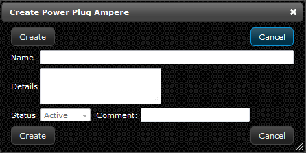
- If you are already in the “Create Power Plug Ampere” window skip to step 3a. If you are not in that window continue to step 2.
- On the navigation menu (left-hand side) click “Extras” and click “Power Plug Amperes” this will open a new tab titled “Power Plug Amperes”
- Within the power plug amperes tab (upper left-hand corner) click the “Create” button. A new window will open up called “Create Power Plug Amperes.”
- Enter the name of the power plug ampere in the “Name” field
- Enter any additional information about the power plug ampere in the “Details” field
- Click “Create”
- If you are already in the “Create Power Plug Backup Source” window skip to step 3a. If you are not in that window continue to step 2.
- On the navigation menu (left-hand side) click “Extras” and click “Power Plug Backup Sources” this will open a new tab titled “Power Plug Backup Sources”
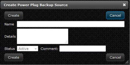
- Within the power plug backup sources tab (upper left-hand corner) click the “Create” button. A new window will open up called “Create Power Plug Backup Source.”
- Enter the name of the power plug backup source in the “Name” field
- Enter any additional information about the power plug backup source in the “Details” field
- Click “Create”
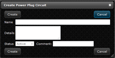
- If you are already in the “Create Power Plug Circuit” window skip to step 3a. If you are not in that window continue to step 2.
- On the navigation menu (left-hand side) click “Extras” and click “Power Plug Circuits” this will open a new tab titled “Power Plug Circuits”
- Within the power plug circuits tab (upper left-hand corner) click the “Create” button. A new window will open up called “Create Power Plug Circuits.”
- Enter the name of the power plug circuit in the “Name” field
- Enter any additional information about the power plug circuit in the “Details” field
- Click “Create”
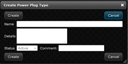
- If you are already in the “Create Power Plug Type” window skip to step 3a. If you are not in that window continue to step 2.
- On the navigation menu (left-hand side) click “Extras” and click called “Power Plug Types” this will open a new tab titled “Power Plug Types”
- Within the power plug types tab (upper left-hand corner) click the “Create” button. A new window will open up called “Create Power Plug Type.”
- Enter the name of the power plug type in the “Name” field
- Enter any additional information about the power plug type in the “Details” field
- Click “Create”
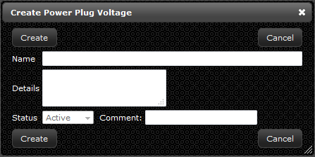
- If you are already in the “Create Power Plug Voltage” window skip to step 3a. If you are not in that window continue to step 2.
- On the navigation menu (left-hand side) click “Extras” and click “Power Plug Voltages” this will open a new tab titled “Power Plug Voltages”
- In the power plug voltages tab (upper left-hand corner) click the “Create” button. A new window will open up called “Create Power Plug Voltage.”
- Enter the name of the power plug voltage in the “Name” field
- Enter any additional information about the power plug voltage in the “Details” field
- Click “Create”
- Manufacturer of the product
- Category of the product
- Model of the product
- Model number of the product
- Generation of the product
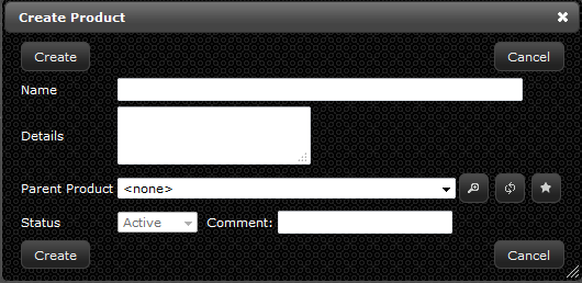
- If you are already in the “Create Product” window skip to step 3a. If you are not in that window continue to step 2.
- On the navigation menu (left-hand side) click “Extras” and click “Products” this will open a new tab titled “Product”
- Within the products tab (upper left-hand corner) click the “Create” button. A new window will open up called “Create Product” or if you are in the “Create Hardware” window, basic tab in the “Product” section, click the star button.
- Enter the manufacturer name of the product in the “Name” field
- Examples: Dell, Oracle, EMC, HP, etc.
- Enter any additional information about the manufacturer name of the product in the “Details” field
- Click “Create”
- In the products tab, click the “Create” button or if you are in the “Create Hardware” window, basic tab, “Product” section, click the star button.
- Enter the category name of the product in the “Name” field
- Examples: Server, Storage, Network, or Infrastructure
- Enter any additional information about the category name of the product in the “Details” field
- Select the manufacturer in the “Parent Product” drop-down menu
- Examples: Dell, Oracle, EMC, HP, etc.
- Click “Create”
- In the products tab, click the “Create” button or if you are in the “Create Hardware” window, basic tab, “Product” section, click the star button.
- Enter the model name of the product in the “Name” field
- Examples: ProLiant, PowerEdge, SunFire, etc.
- Enter any additional information about the model name of the product in the “Details” field
- Select the “Manufacturer – Category” in the “Parent Product” drop-down menu
- Examples: Dell-Server
- Click “Create”
- In the products tab, click the “Create” button or if you are in the “Create Hardware” window, basic tab, “Product” section, click the star button.
- Enter the model number name of the product in the “Name” field
- Examples: DL385, 2900, X4250, etc.
- Enter any additional information about the model number name of the product in the “Details” field
- Select the “Manufacturer – Category – Model” in the “Parent Product” drop-down menu
- Examples: Dell-Server-ProLiant
- Click “Create”
- In the products tab, click the “Create” button or if you are in the “Create Hardware” window, basic tab, “Product” section, click the star button.
- Enter the generation / version name of the product in the “Name” field
- Examples: G5, V2, 7.1, etc
- Enter any additional information about the qualifier name of the product in the “Details” field
- Select the “Manufacturer – Category – Model – Model Number” in the “Parent Product” drop-down menu
- Example: Dell-Server-Proliant-DL385
- Click “Create”
- You can create as many levels of information as needed, but the 5 levels we have just described seem to cover almost all instances of product tracking
- Number of connections the hardware has
- Name of the SAN
- Amount of capacity in GB of the SAN connection
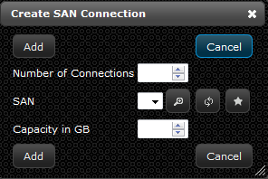
- Enter the amount of SAN connections the hardware obtains in the “Number of Connections” field
- Select the SAN in the “SAN” drop-down menu or create a new “SAN” record by clicking the star button (See Creating a SAN for instructions)
- Enter the amount of capacity the SAN connection has in the “Capacity in GB” field
- Click “Add”
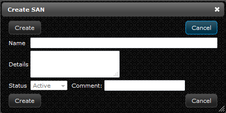
- If you are already in the “Create SAN” window skip to step 3a. If you are not in that window continue to step 2.
- On the navigation menu (left-hand side) click “Extras” and click “SANs” this will open a new tab titled “SANs”
- Within the SANs tab (upper left-hand corner) click the “Create” button. A new window will open up called “Create SAN.”
- Enter the name of the SAN in the “Name” field
- Example: SAN A, SAN B, Storage SAN, etc.
- Enter any additional information about the SAN in the “Details” field
- Click “Create”
- Name of the provider (See Creating a Company for instructions)
- Type of service that the provider performs
- Start date of the service for the hardware
- End date of the service for the hardware
- Discount program of the service (See Creating a Discount Program for instructions)
- Amount of base monthly cost for the service
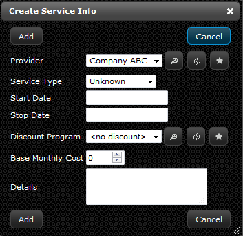
- Select the company that does the service for the hardware in the “Provider” drop-down menu or create a new “Company” record by clicking the star button (See Creating a Company section for instructions)
- Select the type of service the company provides for that hardware in the “Service Type” drop-down menu
- Select a beginning date of the service in the “Start Date” field
- Select an ending date of the service in the “Stop Date” field
- Select a discount program for the company in the “Discount Program” drop-down menu or create a new “Discount Program” record by clicking the star button (See Creating a Discount Program section for instructions)
- Enter a monthly cost in the “Base Monthly Cost” field
- Enter any additional information about the service in the “Details” field
- Click “Add”
- If you are already in the “Create Service Tier” window skip to step 3a. If you are not in that window continue to step 2.
- On the navigation menu (left-hand side) click “Extras” and click “Service Tiers” this will open a new tab titled “Service Tiers”
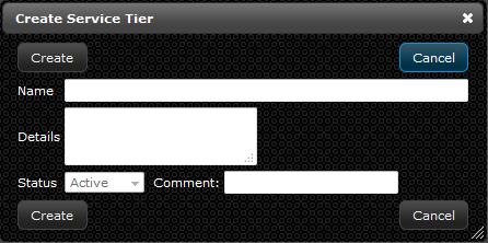
- Within the service tiers tab, in the upper left-hand corner click the “Create” button. A new window will open up called “Create Service Tier.”
- Enter the name of the service tier in the “Name” field
- Examples: Tier 1, Tier 2, Tier 3, Tier 4, etc.
- Enter any additional information about the service tier in the “Details” field
- Click “Create”
- Name of the shape you wish to create
- Which basic shape you are wishing to create, circle or square
- Pixel height of the shape
- Scale width of the shape you are creating
- Degrees of rotation of the shape
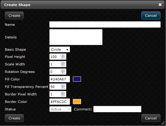
- Disregard the last 4 items (fill color, fill transparency, border pixels, border color) as they have no impact on the shape at the current time, they are placeholders for future functionality
- If you are already in the “Create Shape” window skip to step 3a. If you are not in that window continue to step 2.
- On the navigation menu (left-hand side) click “Extras” and click “Shapes” this will open a new tab titled “Shapes”
- Within the shapes tab (upper left-hand corner) click the “Create” button. A new window will open up called “Create Shape.”
- Enter the name of the shape in the “Name” field
- Examples: Cabinet, Standard Humidity Return, Standard Temperature, etc.
- Enter any additional information about the shape in the “Details” field
- Select what kind of shape to create in the “Basic Shape” drop-down menu
- Define the height of the shape in the “Pixel Height” field
- Enter a value for the width in the “Scale Width” field
- This value is in relation to the height, so if you wanted a square that was 10 high x 20 wide, you would enter 10 for height and 2 for scale width
- Enter a value of rotation for the shape in the “Rotation Degrees” field
- This would be used if you wanted to represent a diamond, you would create a square and rotate it 90 degrees
- Click "Create"
- Name of the SNMP V1 template you wish to create
- IP address or URL for Elicit to communicate with
- Specified read community string: default is public
- Specific OID for the piece of information you are trying to gather
- The regular expression to tell Elicit which data you are specifically looking for
- An adjustment expression for the data being returned to the LiveDC platform
- Specific invalid raw values that are typically returned, which can be excluded. Some sensors return a 0 when in error state.
- If you are already in the “Create SNMP V1 Template” window skip to step 3a. If you are not in that window continue to step 2.
- On the navigation menu (left-hand side) click “Extras” and click “SNMP V1 Templates” this will open a new tab titled “SNMP V1 Templates”
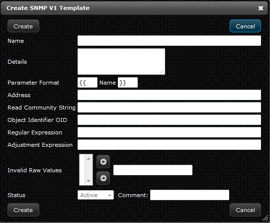
- Within the SNMP V1 templates tab (upper left-hand corner) click the “Create” button. A new window will open up called “Create SNMP V1 Template.”
- Enter the name of the SNMP V1 template in the “Name” field
- Examples: Chatsworth Humidity (Port 1), Chatsworth Power % 30A (Phase XY), etc.
- Enter any additional information about the SNMP V1 template in the “Details” field
- The parameter format can be left as is and provides a way for you to specify what values you need to enter and what the label should be in the pop-up screen
- Enter the Internet Protocol Address in the “Address” field using the defined parameter format
- Example: { {Address} }
- This will prompt the user to enter the specific IP address each time
- Enter the community string in the “Read Community String” field using the defined parameter format
- If standard across the organization, you can enter it here and not have to enter it again when creating a data series
- Enter the object identification number in the “Object Identifier OID” field using the defined parameter format
- Usually very specific for a type of power strip and can be entered here once and used for all power strips of that type
- Example: 1.3.6.1.4.1.319.1.2.1.0
- Define the regular expression in the “Regular Expression” field
- Leave blank as it is not really leveraged at this time
- Define the adjustment expression in the “Adjustment Expression” field
- This will take the raw value received via SNMP and perform an adjustment on that before sending the database for data normalization
- Example: Raw/100
- Add any raw values that are invalid in the “Invalid Raw Values” field and click the left-hand facing arrow, if applicable
- Click “Create”
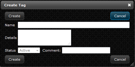
- If you are already in the “Create Tag” window skip to step 3a. If you are not in that window continue to step 2.
- On the navigation menu (left-hand side) click “Extras” and click “Tags” this will open a new tab titled “Tags”
- Within the Tags tab (upper left-hand corner) click the “Create” button. A new window will open up called “Create Tag.”
- Enter the name of the tag in the “Name” field
- Examples: A Side, Row 10, Server, etc.
- Enter any additional information about the Tag in the “Details” field
- Click "Create"
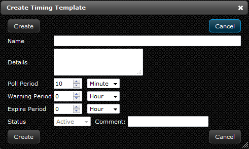
- If you are already in the “Create Timing Template” window skip to step 3a. If you are not in that window continue to step 2.
- On the navigation menu (left-hand side) click “Extras” and click “Timing Templates” this will open a new tab titled “Timing Templates”
- Within the timing templates tab (upper left-hand corner) click the “Create” button. A new window will open up called “Create Timing Template.”
- Enter the name of the timing template in the “Name” field
- Example: 1 minute, 1 hour, 15 minute, etc.
- Enter any additional information about the timing template in the “Details” field
- Define how often the desired poll will take place in the “Poll Period” field
- Define how often the desired warning period will last in the “Warning Period” field
- This warning period will provide alerts if a data series has not communicated within the specified interval
- Define when, if at all, the poll will expire in the “Expire Period” field
- This expire period will provide alerts if a data series has not communicated within the specified interval
- Click "Create"
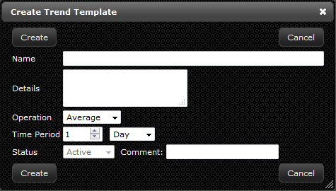
- If you are already in the “Create Trend Template” window skip to step 3a. If you are not in that window continue to step 2.
- On the navigation menu (left-hand side) click “Extras” and click “Trend Templates” this will open a new tab titled “Trend Templates”
- Within the trend templates tab (upper left-hand corner) click the “Create” button. A new window will open up called “Create Trend Template.”
- Enter the name of the trend template in the “Name” field
- Examples: Past 3 Months, Past Day, etc.
- Enter any additional information about the trend template in the “Details” field
- Select what “Operation” you would like to perform on the data from the drop-down menu
- Average, Maximum, Minimum, Median, Sum
- Define time period in which you would like the data to trend in the “Time Period” field
- Example: 30 Days, 1 Month, 24 Hours
- Click "Create"
- On the navigation menu (left-hand side) click “Extras” and click “Uploaded Images” this will open a new tab titled “Upload Images”
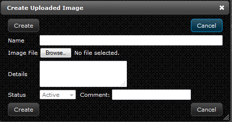
- Within the uploaded images tab (upper left-hand corner) click the “Create” button. A new window will open up called “Create Uploaded Image.”
- Enter the name of the uploaded image in the “Name” field
- Examples: DC Room 1, Storage, POD 2, etc.
- Choose the file that to upload in the “Image File” section
- Enter any additional information about the uploaded image in the “Details” field
- Click "Create"
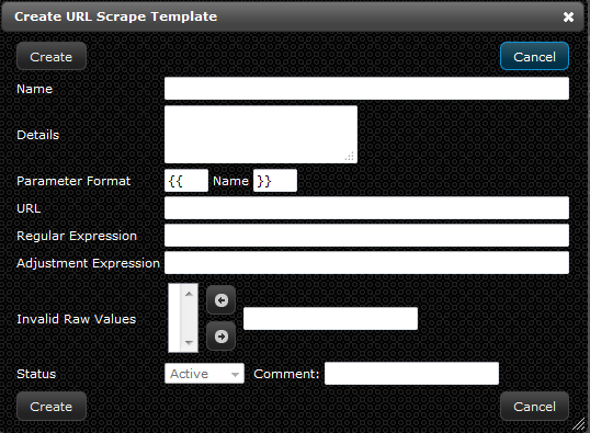
- Name of the URL scrape template
- Specific URL you intend to collect the data from
- Regular expression to tell Elicit where to look within all the text on the web page
- Adjustment expression, if you want to format the data as it enters the LiveDC platform
- Any invalid raw values you do not wish to use in the data series
- If you are already in the “Create URL Scrape Template” window skip to step 3a. If you are not in that window continue to step 2.
- On the navigation menu (left-hand side) click “Extras” and click “URL Scrape Templates” this will open a new tab titled “URL Scrape Templates”
- Within the URL Scrape Templates tab (upper left-hand corner) click the “Create” button. A new window will open up called “Create URL Scrape Template.”
- Enter the name of the URL scrape template in the “Name” field
- Examples: C:\ Drive, Configuration File Collection, CPU, etc.
- Enter any additional information about the URL scrape template in the “Details” field
- Define the format for the parameters of the URL scrape template in the “Parameter Format” fields
- Examples: {{ }}
- Enter the URL that will be used to gather the data in the “URL Scrape Template” field
- Examples: File:///c|public/{ {hostname} }{ {counter} }.txt
- Define the regular expression in the “Regular Expression” field
- Examples: =(\d*)
- Define the adjustment expression in the “Adjustment Expression” field
- Examples: 100-raw
- Add any raw values that are invalid in the “Invalid Raw Values” field and click the left-hand facing arrow, if applicable
- Click "Create"
- If you are already in the “Create Virtual Machine” window skip to step 3a. If you are not in that window continue to step 2.
- On the navigation menu (left-hand side) click “Extras” and click “Virtual Machine Datacenters” this will open a new tab titled “Virtual Machine Datacenters”
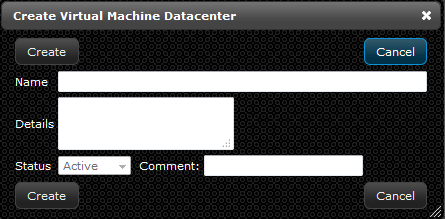
- Within the Virtual Machine Datacenters tab (upper left-hand corner) click the “Create” button. A new window will open up called “Create Virtual Machine Datacenter.”
- Enter the name of the virtual machine datacenter in the “Name” field
- Example: Virtual Room 1
- Enter any additional information about the virtual machine datacenter in the “Details” field
- Click "Create"
- Asset specific information
- Location and physical dimension information regarding the asset
- Data series specific information
- Visual specific information
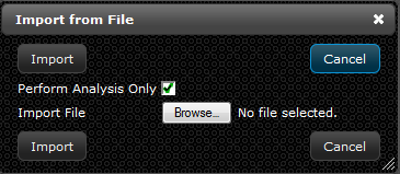
- On the navigation menu (left-hand side) click “Extras” and select the button called “Import from File…” this will open a new window titled “Import from File”
- Click the “Browse” button to select the document to import into LiveDC
- Once the file is selected, you will have the option to perform analysis on the imported data before committing that information to the database
- This helps prevent errors and will give you the results back to ensure all values are correct before actually importing the data
- To perform an analysis on the document, check the box titled “Perform Analysis Only” to green check mark
- Once you have validated that there are no errors and the data looks correct (denoted by performing analysis and getting all green highlighted columns back in the results spreadsheet)
- To actually import the file and commit the data into LiveDC, check the box titled “Perform Analysis Only” to change it to the red X
- Click “Import”
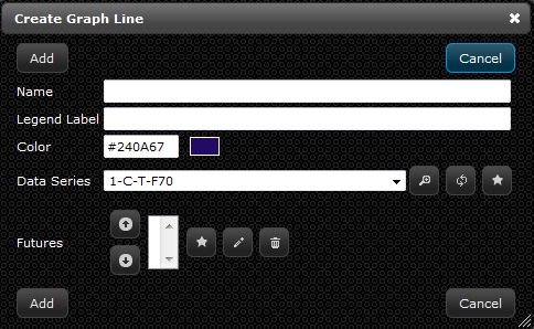
- Enter the following information in the “Create Graph Line” window
- Enter the name of the line in the “Name” field
- Examples: Physical Servers, Average Temperature, Historical Power, etc.
- Enter a name for the legend of this line in the “Legend Label” field
- Examples: Historical, Max Temp, Physical Servers, etc.
- This will appear in the bottom of the graph window
- Select a color for the graph line in the “Color” section
- Select the data series that will provide the data for the graph line in the drop-down menu or create a new data series record by clicking the star button (See Creating a Data Series section for instructions)
- Add a futures line to show how the graph line could change in the future by clicking the star button to create a new “Futures” record
- Enter the name of the graph line future in the “Name” field
- Example: 2.5%
- Enter a label for the legend in the “Legend Label” field
- Example: 2.5%
- Define the period of time the graph will extend into the future in the “Time Period” section
- Enter the amount of future graph lines to come from the historical data in the “Number Per Period” field
- Example: 1 Month
- Enter a formula for the future graph line in the “Formula” field
- Example: prev*1.05
- Define a color for the future graph line in the “Color” field
- Click “Add”
- Click “Add” on the “Create Graph Line” window
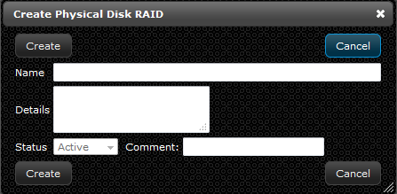
- In the “Create Physical Disk RAID” window enter the following:
- Enter the name of the physical disk RAID in the “Name” field
- Example: Disk Controller
- Enter any additional information about the physical disk RAID in the “Details” field
- Click "Create"
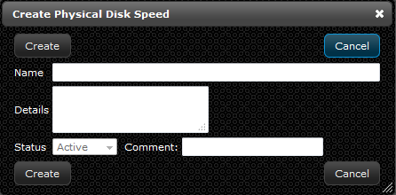
- In the “Create Physical Disk Speed” window enter the following:
- Enter the name of the physical disk speed in the “Name” field
- Enter any additional information about the physical disk speed in the “Details” field
- Click "Create"
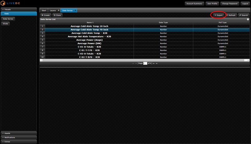
- On the navigation menu (left side), click the desired tab to export records from. To find specific records, utilize LiveDC's robust Search feature (See “How to Use Search” for more information)
- Once the desired records are in a list format on the screen, click “Export” in the top right corner of the screen
- A small window titled “Confirm Export” will appear
- Click "Export"
- LiveDC will compile an Excel spreadsheet of the desired records (these records can be used for the mass import format as a template for what data needs to be entered before importing)
- To import new records (See “Importing from a File” for more information)
Applying a Layer to a Map
Instructions
Customize Display Options When Viewing a Map
Instructions
Opening a Link on a Map
Instructions
Creating a Number Format Template
A number format template takes a raw number value and changes it into usable and contextual metrics. One would typically use this when formatting from Amps to kW or a whole number to a dollar amount or percentage, but it is not limited to that. You will need to gather the following information to create a number format template:
Instructions
Creating a Payment
A payment record, referring to the payment for any asset, is a way to track a payment for a specific device and when/who the payment goes to through the LiveDC platform. You will need to gather the following information before you create a payment record:
Instructions
Creating a Payment Type
A payment type is defining the mode of how the payment is paid. Whether that be a check or automatic deposit, it’s the way to define how you are paying for an asset within the LiveDC platform.
Instructions
Creating a Physical Disk
A physical disk is used to store all server data. LiveDC provides an avenue of tracking these disks for each piece of hardware. It is valuable to track each disk for the purposes of asset management.
Instructions
Creating a Power Plug
The LiveDC platform provides a means of tracking power plugs for each piece of hardware. This is valuable from the standpoint of tracking single and dual corded devices. You will need to gather the following information before creating a power plug:
Instructions
Creating a Power Plug Ampere
LiveDC tracks the amperage that is produced in each power plug. Tracking such information is useful for estimating power usage throughout your data center.
Instructions
Creating a Power Plug Backup Source
Tracking the backup source related to each power plug for hardware is important information to have on hand in the case of a power failure or outage. LiveDC will track the backup power source for each piece of hardware located in your data center.
Instructions
Creating a Power Plug Circuit
LiveDC can track which specific circuit breaker(s) a piece of hardware is connected to. This sort of information is valuable to know for proactively managing scheduled maintenance and powering down hardware.
Instructions
Creating a Power Plug Type
In LiveDC, the type of power plug that is used can be tied back to a specific piece of hardware. We track this information to help identify how many plugs of each type are available in each rack and how many are used.
Instructions
Creating a Power Plug Voltage
Tracking voltage, utilizing the LiveDC platform, is a simple and valuable operation. By entering the voltage information about a specific piece of hardware, you are able to plan for power usage and estimate monthly costs surrounding a single device or many devices.
Instructions
Creating a Product
LiveDC utilizes a parent-child relationship for creating and tracking products. Products tie directly to assets in your data center and make the search function of LiveDC a valuable means of accessing and analyzing your information. You will need to gather the following information before creating a product:
Instructions
Creating a SAN Connection
A SAN (Storage Area Network) connection can be tracked within the LiveDC platform. Tracking this information in LiveDC is valuable, for storage devices especially, to provide an understanding of which SAN fabrics a device is connected to and to determine if there is redundancy. You will need to gather the following information before creating a SAN connection record:
Instructions
Creating a SAN
The SAN (Storage Area Network) is used primarily with storage devices. Tracking this information in LiveDC is valuable, for storage devices especially, to provide an understanding of which SAN fabrics a device is connected to and to determine if there is redundancy between SANs.
Instructions
Creating Service Infos
LiveDC tracks what and who will perform service on each piece of hardware through the service infos section. This information is valuable to track for knowing who to contact in the case of scheduled maintenance, an outage, or failure. You will need to gather the following information before creating a service info record:
Instructions
Creating a Service Tier
In the LiveDC platform, you can track both the requested and actual service tier associated with each piece of hardware. This information is valuable to have when considering recovery times and planning for outages and failures.
Instructions
Creating a Shape
Shapes in LiveDC refer to the boundaries for an influence that are placed on maps. The shapes for an influence can be either a square or a circle, but can be manipulated to represent different sizes for cabinets, PDUs, UPS equipment, etc. A color will fill the shape when it is corresponded to a legend on the map. You will need to gather the following information before creating a shape:
Instructions
Creating a SNMP V1 Template
An SNMP V1 template is a set of rules for Elicit to follow to collect data points from an asset. Utilizing a web address, read community string, and an OID, Elicit will gather information using these instructions and populate data series for use in maps, LiveTiles, and/or graphs. You will need to gather the following information to create an SNMP V1 template:
Instructions
Creating Tags
Tags are what connects almost everything together in LiveDC. Giving a record a tag is very valuable for tracking purposes. Objects with tags are easily found using LiveDC's robust search function. Tags can be used to define location, category of product, type of metric in a data series, client specific tags, or anything else for that matter.
Instructions
Creating a Timing Template
Data series utilize timing templates to tell Elicit how often to collect data from a device. The templates can be configured from polling once every minute to once every month, depending on how important the data is to the end-user.
Instructions
Creating a Trend Template
A trend template tells Elicit to create a data series based upon the data that is in a separate data series. The new data series is created by choosing either the average, maximum, median, minimum, or sum of the data series being polled.
Instructions
Uploading an Image
Uploading an image provides flexibility for the user to customize maps specific to one’s data center. Maps are not limited to just a floor plan though, you can upload virtually any image to construct a map that will depict your data.
Instructions
Creating a URL Scrape Template
A URL scrape template provides an avenue for Elicit to collect data from a specific web page (a web page with no login requirements). This is valuable for collecting data off of the web for many different reasons. Typically the data series created are based upon intelligent assets in the data center that have a web server serving up an HTTP page. You will need to gather the following information prior to creating a URL scrape template:
Instructions
Creating a Virtual Machine Datacenter
Since there is no physical location to put a virtual machine, creating a virtual machine datacenter is the solution. This is the place for virtual machines to reside. It ties the virtual machine to a logical location for tracking purposes.
Instructions
Importing from a File
Importing from a file is the mode of entering large amounts of data records into LiveDC at one time. There is a learning curve to this process, but once this skill is acquired it becomes very useful. Essentially, the user is inputting all of their data records in at the same time and letting LiveDC do the heavy lifting and analysis. Importing from a file is used all across the LiveDC platform, where mostly everything in the software can be imported in a bulk format. You will need to gather the following information prior to importing a file:
Instructions
Creating a Graph Line
Instructions
Creating a Physical Disk RAID
A physical disk RAID is a redundant array of independent disks. LiveDC provides an avenue for tracking these disks for each piece of hardware. It is valuable to track each disk for the purposes of asset management.
Instructions
Creating a Physical Disk Speed
LiveDC provides an avenue for tracking these disks for each piece of hardware. It is valuable to track each disk speed for the purposes of asset management.
Instructions
Exporting a File
Instructions
